Simulate circuits in your web-browser at: http://androidcircuitsolver.com/app.html
As I approached my senior year for my B.S. in Electrical Engineering, I wanted to create
something that most people hadn't created before, a circuit simulator! It was about the
experience, the learning, and the the journey itself. I put together this application to
package my knowledge in Electrical Engineering to some day help another student have
an easier time in their scholastic pursuits and in turn teach them about circuits.
Circuit Solver is far from perfect and there are lots of things that could be optimized.
It will however, simulate a majority of linear Circuits and a decent amount of smaller
scale Non-Linear Circuits. If this app helps you in any way, i'd appreciate you spreading
the word to help support my efforts, Thanks!
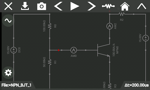
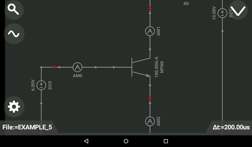
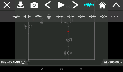
Think of Circuit Solver as an electronic circuit board, you drag your electrical components
and place them on one at a time. You hook up some sources and you place some meters
to read the values. If you need to analyze the waveform, grab some electrical leads and
view them with an oscilloscope. There are many SPICE tools out there for PC such as
Multisim, LTSpice, and PSpice. Circuit Solver doesn't compare to their raw power
but it is optimized to run on mobile devices which makes it both portable and easily
accessible to anyone in need of circuit solutions. Circuit Solver strives to verify Ohm's law,
Kirchhoff's current and voltage laws by creating models that are both stable and efficient.
Make circuit solver your first step in circuit design!
DC Simulation:
To simulate the circuits, a matrix is defined based on all the components inside the circuit.
The application solves the circuit using matrix manipulations such as LU-Decomposition
and matrix inversion. DC Analysis is completed by writing a series of nodal equations.
The equations are solved simultaneously to obtain a unique solution.
Transient Simulation:
In transient simulation we use numerical integration to determine the response of RLC
circuits. Numerical integration allows for one to solve for discrete moments of time and
in effect integrate their response. This application only supports the Backward Euler method.
Non Linear Simulation:
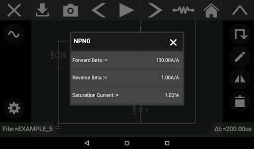
Non linear simulation is used for components such as diodes, LEDs, and transistors.
The solver first guesses the approximate value of the solution and is refined through the
use of a Newton-Raphson process. It utilizes linear approximation to predict the answer
through successive iterations.
Built-in-Oscilloscope:
Visualize waveforms through the use of the built in oscilloscope. To use this feature
simply link either a volt meter or an amp meter to the graph by tapping on them and
pressing the eye, in order to view the wave.
Saving Schematics/Circuits:
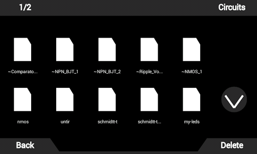
Save your circuits on your device to use anywhere you go and at any time. You may
also capture screen shots of the circuits you build. These screen shots are saved
locally on your device.
List of Components:
+Resistor
+Capacitor
+Inductor
+Ideal Operational Amplifier
+NMOSFET
+PMOSFET
+PNP Bipolar Junction Transistor
+NPN Bipolar Junction Transistor
+AC Voltage Source
+AC Current Source
+DC Voltage Source
+DC Current Source
+Square Voltage Source
+Triangle Current Source
+Sawtooth Current Source
+Triangle Voltage Source
+Sawtooth Voltage Source
+Amp Meter
+Ohm Meter
+Volt Meter
+Diode
+Red LED
+Green LED
+Blue LED
+Yellow LED
+Orange LED
+Wire
+Voltage Controlled Voltage Source (VCVS)
+Voltage Controlled Current Source (VCCS)
+Current Controlled Current Source (CCCS)
+Current Controlled Voltage Source (CCVS)
+Switch (SPST)
+Switch (SPDT)
+Ground
+Transformer
+AND Gate
+OR Gate
+NOR Gate
+NAND Gate
+Inverter
+Potentiometer
+XOR Gate
+XNOR Gate
+Zener Diode
+Push Button (NC)
+Push Button (NO)
Improved loading times.
Fixed errors when reading circuits.
Updated wire voltage reading.
Updated gmin stepping.
Fixed LED drawings issues.
Revised device models.
Updated switches.
Added settings for integration methods.
Removed grounding requirement for controlled sources.
Performance boost.
More bug fixes!
Updated for initial solution.
Fixed rendering issues.
Performance Boosts.
Improved Performance.
Improved Performance.
More updates!
Minor Edits.
Fine tuning simulation parameters.
Updated UI Logic.
Minor Modifications.
Cleaning up bugs.
Minor fixes.
Fixed fuse errors.
Fixed drawing issues.
Minor Cosmetic Changes.
Minor Cosmetic Changes.
Fixed Bugs.
Fixed Resizing Error.
Fixed possible Device Pixel Ratio error.
Minor Performance Increase.
Updated logic gate behaviors.
UI Editing.
Minor Update.
Minor Performance Boost.
Bug Squash.
Minor Performance Updates.
Removed Diode / LED Undefined parameter.
UI Improvements.
Minor Bug Fixes.
Fixed element update issue.
Update.
Fixed file reading issue.
Minor UI Updates for Speed.
Fixed Minor UI Scaling Issues.
Minor Graphics Fix.
Minor UI Patch.
Removed support for android API 23.
Fixes for file operations.
Update.
Minor UI Drawing Fix.
Minor Update.
More Fixes :D
Fixes for Bugs.
System Update.
FET fix.
Proper name tags for multiplexed elements.
Bug Fix.
Minor Patch Update.
Fixer Uppers.
+Saw Wave (Voltage)
+Saw Wave (Current)
+Triangle Wave (Voltage)
+Triangle Wave (Current)
Hardware Acceleration.
Tsk. Tsk. Android.
Updated!
Increased Simulation Speed.
Tag Name Changed.
Edited Examples
Eh.
Rendering Updates.
Speed Optimization.
Bug Fixes.
Model Changes.
Cosmetic Fixes.
Text Fix.
Hue hue hue.
Resolution Changes.
Eh?
Application Not Responding (ANR) Fixes.
Patch Work.
UI Cleanup.
Bug Fixes.
Electrical Model Updates.
Electrical Model Changes.
Diode Model Updated.
Graph Resolution Increased.
Automatic Timestep Tweaking.
Option Added for Automatic Time Step Calculation.Removal of Ads.
Minor Modifications
>:I
Diode Model Improvements.
Duty Cycle Square Waves.
Tweaking Convergence Parameters.
More Stability Fixes.
Bug Fixes.
Convergence Improvements.
Minor Fixes.
Improved Matrix Library.
Synchronization.
Possible ANR Fix.
Convergence Helper.
Aspect Ratio Patch.
Dun dun dun dunnnnn?
Dun Dun Dun Dunnnnn
Bug Fixes.
Meter Graphs!
Simulation Speed Optimization.
Transistor Speed Up.
Precision Update.

 Sony Xperia XA2
